DIY wood lathe idea

I found myself needing to make some turned tool handles. In the past I’d done this on one of my metalworking lathes but it is a huge pain to clean all the dust and chips out of the machine so I decided it was time to get a simple wood lathe. I thought about buying one from Harbor Freight or Grizzly, but the problem I kept running into was that the length I needed required quite an expensive lathe and I wasn’t about to pay several hundred dollars or more for that, especially when I don’t need or want to turn bowls. My requirements were a swing of only about 2 inches but at least 36 inches between centers. 1/3-1/2 HP would be plenty.

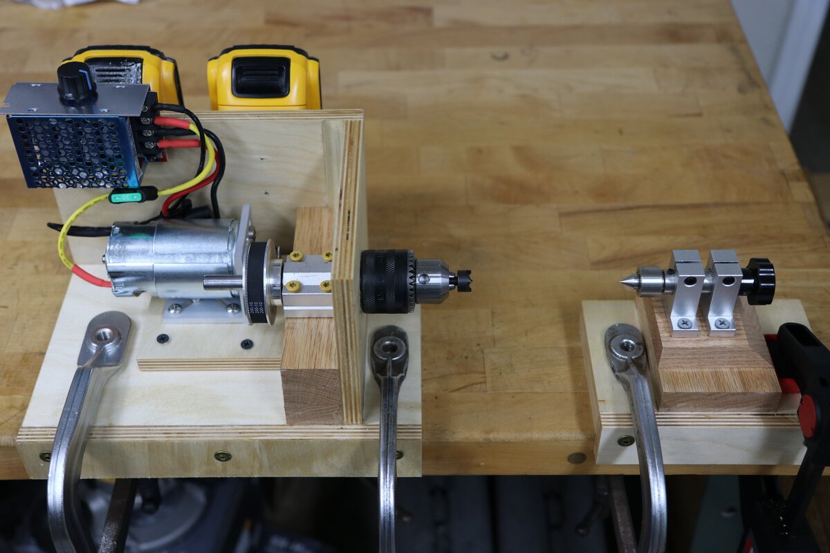
I ended up coming up with this idea which I thought was pretty clever: I built a separate headstock and tailstock using parts from Amazon with the bases made from plywood. They are placed on a stout workbench, secured with clamps, and then the workbench becomes the bed of the lathe. There is a small amount of adjustment on the tailstock quill but otherwise it can accommodate different size workpieces just by moving the parts on the workbench and re-clamping them. All said and done it cost me about $100 plus some scrap wood, and it works extremely well.

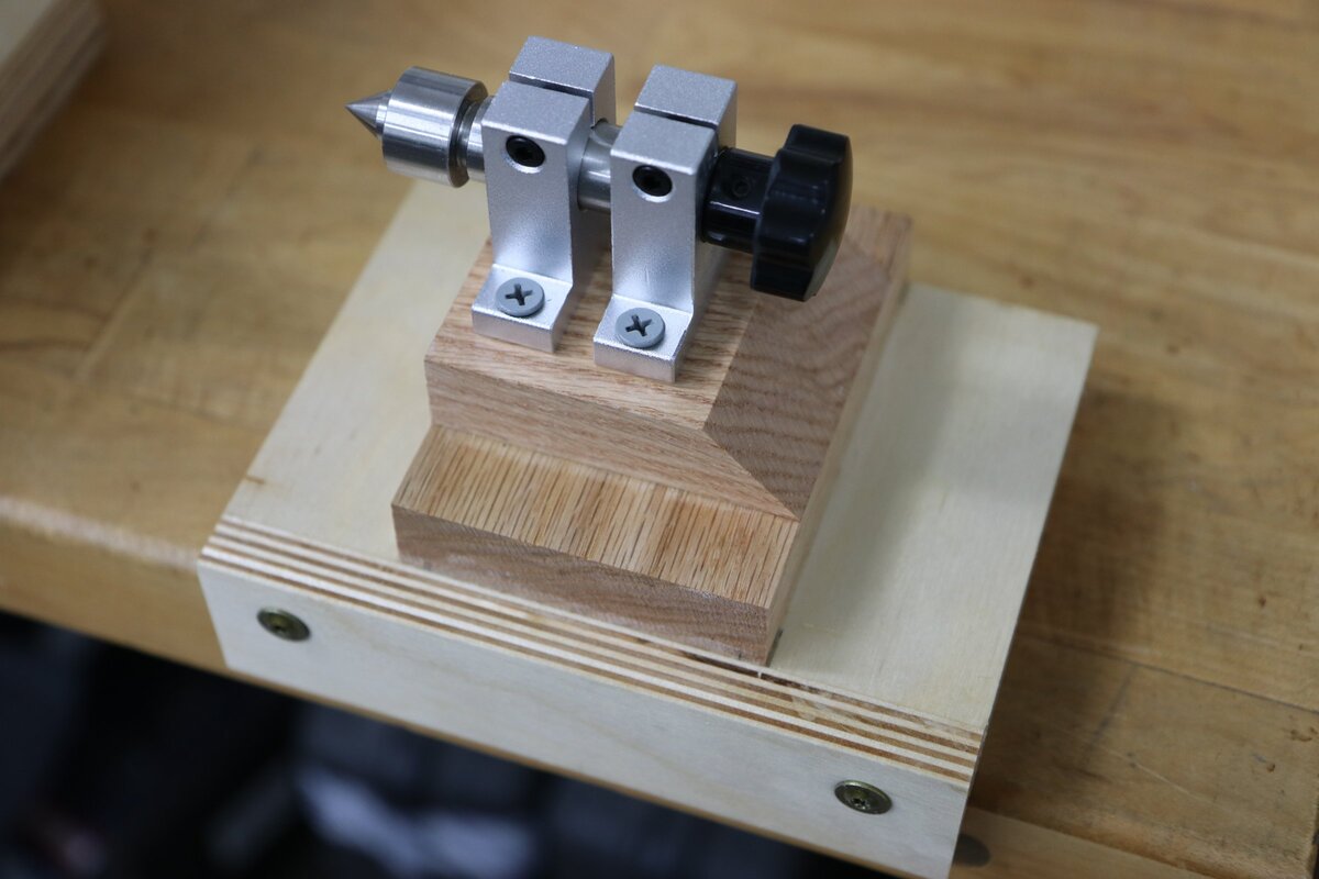
The tailstock is very simple. It is one of these from Amazon mounted to a plywood base, with a second guide rod support added so I could screw it down in four places instead of just two.

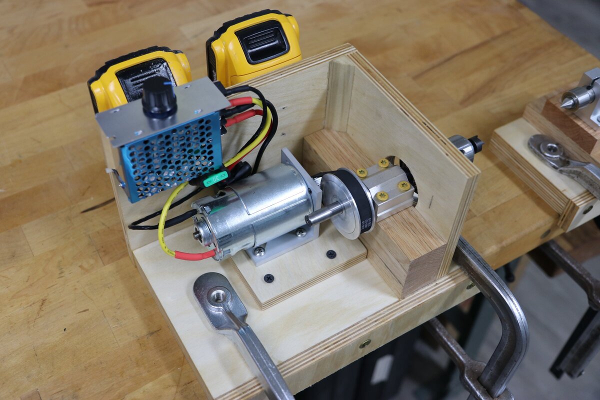
The headstock is built around this assembly:
https://www.amazon.com/dp/B08DXXY9J4
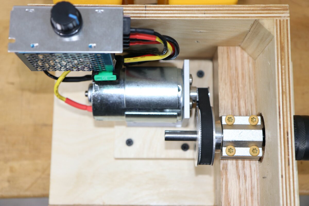
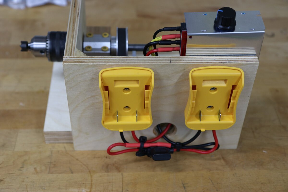
The power source is a 400W 48V 997 DC motor I found on sale for $20. It drives the spindle via 10mm wide GT2 timing belt, 20t pulley on the motor and 80t on the spindle for 4:1 reduction. All of those were cheapie parts from Amazon. Power is two Dewalt 20V max packs in series using “power wheels adapters”, and speed control is via a 30A PWM unit, also from Amazon.

The base of each is 1" thick birch plywood and has space for clamps. There is a lip under the front edge of each base so they align on the edge of the workbench. I made a couple different tool rests from scrap wood that likewise can be clamped to the workbench.

Performance was great. The motor has plenty of power–maybe not for a big bowl but it’s more than enough for the swing I want. It’s obviously light duty but it seems well sized for the work I am doing, and I think it’s a great idea for doing turning on a budget and maybe it will help inspire some people. The same idea could be upscaled for doing larger work.

That’s amazing, dude! I would love to see photos and a parts list.

I don’t know anything about building this kind of thing. Why did you go with the battery packs instead of a power supply? Could you have used a corded drill or grinder to drive the shaft directly? Thanks!

I’m not anywhere near it right now so I can’t take pictures at the moment but I will be able to do so in a few days.

I went with the battery packs for two reasons. First was that it was very economical. I already have a bunch of Dewalt batteries so all I had to buy was a pair of the battery socket adapters that the batteries could plug into. Those were $15.99 for a 2-pack on Amazon and that came with built-in fuse holders and extra fuses. An AC power supply would absolutely work but there was no way I could get one for anywhere close to that cheap. I could have used an AC motor–and probably would have if I had an appropriate one lying around–but those were also more costly. The second reason was so I can use it outdoors for easy cleanup and not have to mess with a power cord. It can be clamped to anything stout and heavy, like a large piece of lumber sitting across a pair of sawhorses.

I absolutely could have used a drill or other tool to drive the shaft directly. In fact I thought about going for the ultra-cheap option of just using a cordless drill as the power source but controlling the speed with any of the drills I currently own would be a bit awkward, plus I wanted a higher top RPM for small parts. I thought about other tools but they all had disadvantages. A router would be too fast, same with most grinders. Angle grinders would also be difficult to attach drive devices to since they have a threaded spindle. Cost was also a concern. After poking around on Amazon I found a 997 size DC motor, that was pretty nice, it was on sale for $20. It was too fast to couple directly to the spindle but pulleys are cheap on Amazon. I didn’t need the power of using two batteries but it just happened to work out with the voltage of the motor that was on sale. There are also 24V motors available, those would run on just one battery, but they were not on sale so it was cheaper to buy the 48V motor and two battery adapters than it was to buy a 24V motor and 1 adapter. So when I thought about the total cost of the power source, motor, speed control device using that solution came out ahead.
Here are the parts I used. I can see the motor is no longer on sale so other prices might have changed too, it might be worth browsing around and seeing if there are better deals.

Parts for Headstock
Motor Amazon.com
PWM Speed controller* Amazon.com
Motor mounting bracket Amazon.com
Battery adapters Amazon.com
Drive belt (the pulleys in this set will not be needed) Amazon.com
Spindle pulley Amazon.com
Motor pulley Amazon.com
Spur center https://www.amazon.com/dp/B09JW5JDV7
Spindle kit (many parts will not be used) linked in my original post

Tailstock Parts:
Main tailstock assembly is linked in my original post
Extra support bracket for tailstock (only one needed) Amazon.com

Other than those parts I used the following from my pile of spares:
Wood screws for mounting the battery holders and securing the tailstock, motor mount, and spindle bearing housing to the wooden bases.
Double sided tape to mount the speed control
Four short M5 machine screws & washers for bolting the motor to the mounting bracket
Offcuts of oak lumber and 1/2in baltic birch plywood. The oak doesn’t need to be oak, that’s just what I had lying around, but it should be hardwood.
A short piece of 12awg wire
Spade terminals & heat shrink tubing

The construction is extremely simple as the photos will make clear in a few days. This also requires 4 clamps to secure to the workbench or whatever you’re using as the bed, plus an extra clamp or two for whatever you’re going to use as a tool rest.

*If I had to do it again I’d buy a different speed control that had the fwd/stop/brake switch wired remotely. The controller linked above works well but the switch is tiny and hard to access. I’m going to end up desoldering it and wiring a remote switch but it would be easier to just a buy a different one that’s already set up like that.

1 Like

Thank you sir! That’s amazing.


I think the photos make things pretty self-explanatory, there’s nothing really special about how I put the wood together, it could be improved upon with some thought I just went for quick-and-dirty. As for dimensions I didn’t do much measuring: the base of the tailstock is 6" x 4" x 1" thick not counting the lip on the front. The base of the headstock is 10" x 6" x 1" thick not counting the lip. I put two layers of 3/4" oak boards between the metal tailstock assembly and the plywood base. The wood was glued together first, starter holes drilled, then the metal parts were screwed down with long wood screws that go all the way through the oak and into the plywood.
The construction of the headstock is pretty similar. The bearing housing for the spindle is mounted to a hardwood block. Again I made this from oak scraps I had lying around but any hardwood should work. The block is the same 6" depth as the base, is cut to the same width as the bearing housing, and is cut so that the center height matches the tailstock. I attached two extra pieces of plywood to stiffen up the assembly and provide a convenient place to mount the batteries.

Here are the dimensions of various pieces. I wouldn’t get too caught up in the exact measurements I used as I pretty much pulled them of thin air without doing much experimenting, but in case they are useful:
Tailstock
base: 6" x 4" x 1" baltic birch ply (made by laminating 2 layers of 1/2in)
intermediate blocks: 4" x 3" x .75" and 3" x 3" x .75" oak
Front lip: 6" x 1.5" x .5" ply

Headstock:
base: 10" x 6" x 1" ply
Spindle mounting block: 6" x 55mm x just a little over 2" in height–I made the block oversize then planed the height to match the tailstock rather than cut to a measurement. Oak.
front piece: 6" x 5" x .5" ply with a 1.75" hole cut for the spindle to pass through.
battery board: 8.5" x 5" x 1/2" ply with a 1" hole cut & edges rounded over for the wires & fuse holder to pass through.
Motor mount base: 4" x 4" x .5" ply
Front lip: 10" x 1.5" x 1/2" ply

You can see I glued a small piece of what looks like 45deg molding where the front piece and battery board meet. That was just to reinforce the joint. It’s probably not structurally necessary but if I were doing this again I’d make it bigger so it could hold the switch for the speed control and also have a spot to store the chuck key. As it stands I plan on gluing a block of material somewhere to make a chuck key holder but I haven’t done it yet. I also accidentally glued on the front piece upside down so the hole doesn’t line up with the chuck correctly, but it still worked so I got lucky!

The electrical wiring is extremely simple. There are only 4 connections on the speed controller. Motor +/- and Battery pack +/-.
I wired Motor + to the motor’s + terminal using the fuse holder which came with the speed controller and the supplied 30A fuse.
I wired Motor - directly to the motor’s - terminal using an extra piece of 12awg wire from my wire scrap bin.
I connected the two battery holders in series using their own leads. The remaining + terminal from the battery holder went to Battery + on the speed control with the other fuse holder already inline there. The - terminal from the battery adapter was wired to Battery - on the speed control.
I noticed that the motor mounting bracket was blocking the air intake slots on the front of the motor so I drilled 4 holes in it, the slots are not 100% open now but the motor manages to move an impressive amount of air through itself so I don’t think there will be any problems keeping it cool.

1 Like