Here’s a clamp I’ve never seen before. It looks like an ordinary F-clamp, except the jaw with the screw behind it doesn’t spin. It moves like a piston. The screw is actually dual-threaded, with opposing threads. The upper threads engage the jaw cylinder from the inside, which is apparently keyed so it doesn’t spin. Supposedly that increases clamping force AND speed, though I’m not sure that’s possible. But the non-spinning jaw pad is pretty cool.
The principle of using double threads with different pitches or different directions to control motion is well known. I’ve built super-precision X/Y stages for lab testing which used this principle. But like you said, I’m skeptical of the claim that it is simultaneously faster and generates more force. It’s really no different than levers or gears, you can trade speed for force and vice-versa but you don’t get both. Maybe this has some kind of “auto-shifting” function (for lack of a better term) that allows it to run fast at first and once it encounters resistance it then works in “low gear” to allow stronger clamping?
1 Like
I’m glad I wasn’t crazy to think their claims of higher speed AND greater force were iffy.
The mechanism appears to be just a double-threaded bolt and two threaded sleeves. No “gear-shifts” visible. So I’m calling bunk on that claim. Threading that bolt in opposite directions would increase speed and DECREASE force, no?
But I wonder why they need the second thread at all. They could just thread the jaw into the bolt and hold that bolt in position with a stop collar or something, so in effect the second thread would have a thread pitch of zero. Or they could just let the jaw ride against the bolt, which is threaded into the clamp body. Either way, the jaw would move up and down without spinning.
And as it is, one of the threads has to be left-handed. Is it more expensive to thread a bolt left-handed than right-handed? I’m sure it’s more expensive than no threads.
But I can’t see what keeps the jaw from spinning. I assumed it’s keyed somehow, so a protrusion on the jaw rides in a groove machined into the hole wall. But maybe that’s not the case, and that second thread is necessary for some reason.
Here’s a diagram of the mechanism.

If the goal was simply to stop the jaw from rotating then you’re right, there’s no need for the double thread at all.
The double threads work like gears, depending on what the thread direction is you either add or subtract the pitches together, and there’s various goals possible. Their claims are conflicting which makes it hard to tell what’s going on here. Depending on how they designed it it’s possible they could be getting extra force or extra speed.
If the parts are arranged like the photograph you posted and one thread is left-handed while the other is right-handed this has the effect of moving faster but providing less force. Basically the two pitches are added together.
Example 1: suppose the parts are arranged like the photo, the outer sleeve is fixed in place. Handle is at the bottom, the larger threads are 1/2-20 RH and the smaller threads are 1/4-28LH. Suppose we screw the handle “in” one revolution. This makes the central shaft and plunger move upward (per the photo) by 1/20th of an inch. At the same time, the plunger has “unscrewed” from the central shaft by that same one revolution, so the plunger moves forward another 1/28th, so the total motion is .0857", greater than either thread would have moved the device on its own, and therefore generating lower pressure.
Example 2: same assumptions, except now the smaller thread is 1/4-28RH. As above we screw in the handle one revolution, thus the central shaft and plunger move up the same 1/20th of an inch. But at the same time, the smaller threads in the plunger are pulling it back down 1/28th. So now we subtract, 1/28th from 1/20, and the total motion of the plunger is 0.014, less than either pitch on its own. This can be used for super fine precision, like the X-Y stage I built, fine focus knobs on a microscope, telescope, etc.
Thanks for the explanation!
I could see the need for two threads if they wanted to move that jaw slower (and with more force) than is possible with a single standard threads, which I’m thinking must be limited in how low their pitch can go (maybe by the tooth size or depth, or maybe by strength requirements or machining limitations.) But then the two threads would be in the same direction.
But here, the two threads are in different directions, which has the effect of increasing the total pitch, as you say.
So why couldn’t they just make one screw with a larger pitch?
And what’s wrong with standard acme threads? We use lots of clamps with acme threads, and are pretty happy with them.
I’d pay a little extra for a non-spinning jaw on an F-clamp though. Such a clamp would be less expensive (I assume) than a parallel-jaw clamp, while offering one of the advantages of parallel-jaw clamps.
As to why they didn’t use a screw with a coarse pitch like an acme screw? Honestly a good question. I’m not sure if it’s possible to roll acme threads, if it isn’t or if it’s complicated (which I suspect) then it would be more costly to make acme threaded parts. But at the same time you would need fewer parts with an acme thread, so I suspect acme threads probably are cheaper in the end which is why they are so common on clamps.
Normally whenever I see this kind of “double screw” mechanism used it’s when the goal is to make the effective pitch as fine as possible. You could theoretically cut any pitch thread but there’s a practical limit on how fine you can make them in reality. When threads get super fine they become very delicate and the tolerances needed to make them fit become impractically tight, so using this method to effectively get super-fine threads while using easier to cut pitches makes sense. But to make a clamp act faster? A good coarse acme thread ought to do that just fine. And nevermind the fact that with clamps like this there isn’t much motion with the clamping screw anyway, the vast majority of the slack is taken up just by moving the jaw along the bar.
1 Like
The idea is to keep the post moving linear with no rotation even as it binds up.
Fine thread tends to hold more force in axis than corse thread (think down the bolt center)
When they say faster I wonder if they mean more clamping into place faster. I know when I use a basic F clamp I find I often have to adjust or repositions as the pad does rotate on me as it binds in. This wouldn’t do that
meanwhile I wonder of the parallel jaw clamp made this obsolete.
Yes, they wanted the post to move without rotation, but two threads aren’t sufficient for that. They also need a keyway or something to keep the post from rotating. And they aren’t necessary either; if there’s a keyway, just one thread would work, as discussed earlier.
Parallel clamps might have helped make them obsolete, but they’re expensive. Perhaps these dual-thread clamps would be cheaper.
New Rockler Piston F-Clamps Can Generate 1 Ton of Clamping Force (toolguyd.com)
You might take a look at this discussion
1 Like
LOL - thanks fred.
interesting items all around. I could see a need for it but I think for the money I’d buy a paralell. Only thing would be if I was metalworking.
would be nice to see this mechanism with a wider jaw piece or even a removeable set of jaws. (round and wide block)
1 Like
Thanks fred! That’s an interesting discussion about how to clamp glued parts, and how much force is really needed.
It’s still something of a mystery to me why Piher decided to use two threads in these clamps instead of one. But I guess it worked okay, if Rockler decided to offer a version.
Those Urko clamps that fred posted about in that earlier conversation are interesting too. They have a single acme-style thread, and use two steel balls to decouple the piston from the threaded crank.
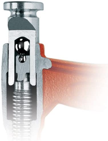
I assume the piston is keyed or slotted so it doesn’t rotate. Stuart mentions that bought a pair but he couldn’t get the jaw faces to parallelize, resulting in marred wood. But I’d guess you could add jaw pads, or just file down the skewed jaw face. Come to that, I wonder why they don’t have swiveling jaws, like most F-clamps (or C-clamps for that matter.)
RKA mentions that Bessey also makes piston-style F-clamps, but glancing at their online catalog, I don’t see anything like that. Too bad; maybe they would be cheaper than the Pihers or the Rockler version.
In the shower this morning, I got to thinking about the two steel balls pressing together. There must be an incredible amount of pressure on that microscopically small contact point. I wonder why they couldn’t just grind the contacting surfaces reasonably flat and put grease in between.
Maybe it has to do with friction at the intersection of the 2 surfaces. The ball bearings would tend to roll while flats - even with a lubricant might eventually gall. (coefficient of rolling friction versus sliding friction). The smaller contact area might also reduce any propensity for galling. Toolguyd-Stuart with his PhD in material science - might have a better take on this.
Cost savings is my guess. I’ve used that trick before, it’s a very cheap way to make a low-friction thrust bearing. Though like you said there is a massive amount of stress at the contact point, the balls will certainly wear there, though for an application like this it doesn’t matter if there is because the clamps are being re-tightened every time they are used so there’s no opportunity for play to develop.
Aha. I can see your point about tightening if the balls simply develop a flat spot at the contact point. But might there not be cracking or spalling at that point? Then the friction would be pretty high. I’ve seen hardened steel crack like glass given enough stress.
But maybe the steel balls aren’t hardened, or one is hardened and the other is not.
I don’t see how the balls will roll, if “rolling” means rotating about an axis that doesn’t go through the contact point. These two balls will “spin” relative to each other, not “roll.” I would guess that means sliding friction and not rolling friction, but I’m no expert.
I can see galling might be an issue, but hardened steel doesn’t gall much that I’m aware of. Or the parts could be coated with TiN or something. Or the parts could be impregnated with moly or graphite. Etc.
I’m sure that cracking is possible if the loads were high enough. I only used this for fairly low load applications, probably no more than 100lbs pressing the two 3/8" diameter balls together. I did take the equipment apart and put it back together again many times and I never observed any cracking or obvious deformation under those conditions, just a tiny spot at the point of contact which I assumed must be worn slightly flat but I never bothered to examine under a microscope. I was using hardened steel bearing balls. They were not plated but they most certainly were hard. Also the balls were not allowed to “roll”, as each one was pressed into its own hollow pocket–one in the end of the shaft whose motion I was controlling, and the other in the end of the bolt used to take up the slack. I used automotive wheel bearing grease with Moly as lubricant.
1 Like